ITC™ MODEL 100 ZERO SYSTEMS
ITC 内螺纹测量指示规100系统
美国南规制造公司出品
OPERATING INSTRUCTIONS FOR INTERNAL THREAD COMPARATOR
内螺纹指示规操作指南
MOUNTING GAGE SEGMENTS
固定指示规螺纹测头
Clean mounting surface on frame and segments. Locating surfaces must be free of any lint or dirt to avoid incorrect seating of segments. Attach segments to frame with mounting screws. Segments are interchangeable top to bottom. Depress operating lever to be sure bottoms of segments match face to face (not cocked)
擦试干净框架和螺纹测头的表面表面不得有任何线头或者污垢,避免螺纹测头的不正确就位。用紧固螺丝把螺纹测头装上。螺纹测头从上到下的顺序进行更换。按下操作手柄,确保底部的螺纹测头与被测螺纹面到面贴合(不要翘起)。
SETTING THE ITC THREAD COMPARATOR
ITC螺纹指示规的设定
The comparator is set with a single master ring gage.To engage the master ring gage, depress the operating lever at the back of the comparator and place the master ring gage on the segments. Gently rock the master ring gage to ensure that it is seated correctly. 这个指示规通过一个环规标准件进行设定。为了与标准环规吻合,按下操作手柄,把环规标准件放在螺纹测头上。轻轻摇摆环规标准件到正确的放置位置。
MOUNTING THE ELECTRONIC INDICATOR
固定数显读数表
The digital electronic indicator is held in place by a clamp nut. Preload the indicator to .250” on the digital readout. Lock the indicator with the clamp nut. Push the clear button or zero button to zero the indicator. Rock the master ring gage slightly to check seating and push the zero or clear button again to ensure ITC is set.预置读数到0.25英寸。.数显读数表通过一个夹持螺母来进行固定。通过夹持螺母固定数显表按复位键或者零位键让数显表归零。轻轻摇动环规标准件检查正确放置,再次按零位键或者复位键确保指示规已经设定好。
Depress operating lever and remove master ring gage. If SPC operation is required consult with indicator manual for data management and programing. 按下操作手柄,取出环规标准件。如果需要SPC操作,请查阅读数表手册以获取数据管理和编程。
MOUNTING DIAL INDICATOR
固定指针表
The dial indicator is held in place by a clamp nut. Preload the indicator at least one full revolution and adjust the indicator to read zero. Lock the indicator in place with the clamp nut. Rock the master ring very slightly to check seating. Loosen the bezel clamp on the indicator face and locate indicator pointer at zero. Adjust indicator tolerance hands (if available) to tolerance limits. Tighten the bezel lock screw.
指针表通过夹持螺母进行放置。预置至少一次全量程和调整到读数零位。通过夹持螺母琐紧指针表.轻轻摇摆环规标准件以检查放置位置。 松开指示器表面上的挡板夹,将指示器指针定位在零位。将指示器公差指针(如果可用)调整到公差限值。拧紧挡板琐紧螺钉。
CAUTION
提示
DO NOT ROTATE THE MASTER RING GAGE OR THE PART ON THE SEGMENTS AS THIS COULD CAUSE DAMAGE AND WEAR TO THE GAGE AND OR SEGMENTS.
环规标准件或者工件放置在指示规的螺纹测头上后,不要旋转,因为这样会导致指示规的损坏和测头的磨损。
Erroneous readings may result from rotating the gage or the part due to the helical pull of the thread path. After placing the master ring or the part on the segments they should be rocked slightly to ensure that they are seated properly. If readings at multiple locations are required the operating lever should be depressed to remove the gaging pressure and relocate the part and then release operating lever to read size.
由于螺纹路径的螺旋拉力,旋转量规或工件可能会导致读数错误。将环规标准件或工件放置在螺纹测头上后,应轻轻摇动,以确保其正确就位。如果需要在多个位置读取读数,应按下操作手柄以消除测量压力并重新定位工件,然后松开操作手柄以读取尺寸。

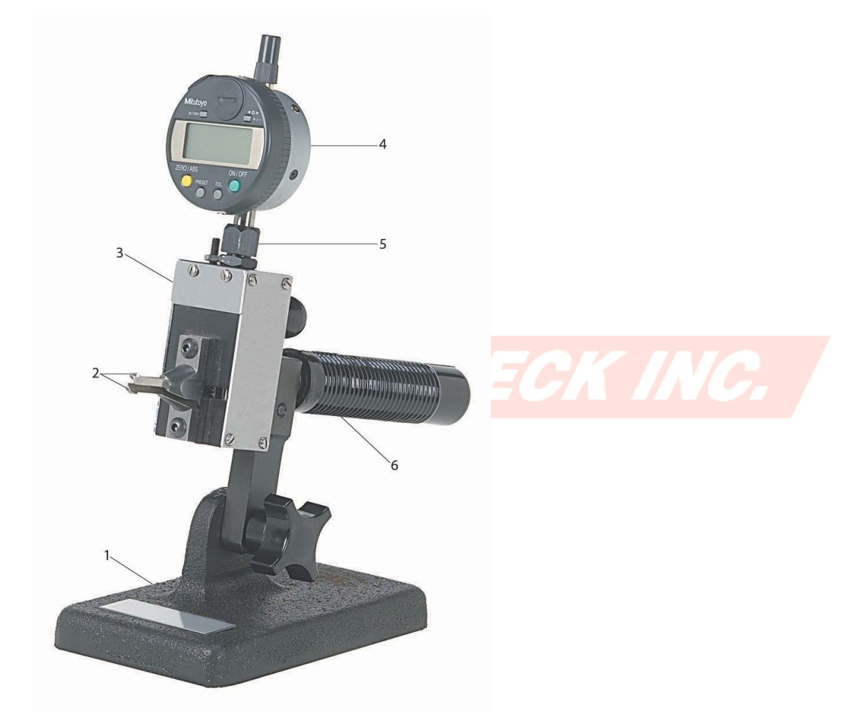
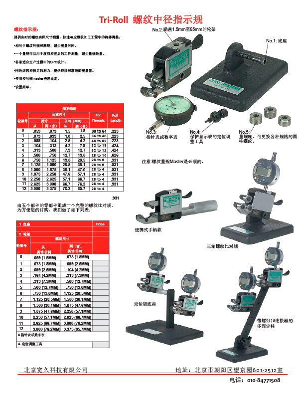
1. Base w/adapter – One base is applicable to all frames
底座:适用所有的尺寸框架
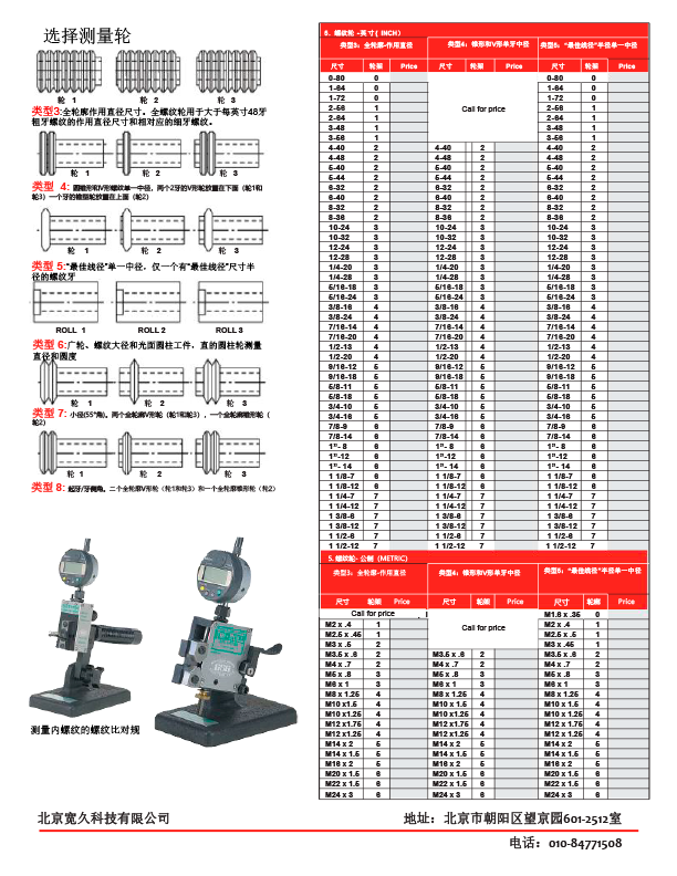
2. Segments – Functional segments or single element pitch diameters segments to check the maximum or minimum limits of size.
螺纹测头:作用中径或单一中径的螺纹测头,测量最大或者最小的尺寸极限。
3. Gage Frame – 3 gage frames are available from .189 up to 8.00 inches in diameter
指示规框架:有3种框架可选,测量直径尺寸从0.189英寸到8英寸。
4. Indicators – Digital electronic indicators w/output or AGD dial indicators w/.0001” graduations and adjustable tolerance hands
读数表:数显表,带输出,或者指针表。
5. Indicator Clamp Nut – Supplied with frame
夹持螺母
6. Handle – For hand held applications
操作手柄
Master Set Ring Gages are supplied with a functional diameter value and pitch diameter value. The functional diameter is the actual measured pitch diameter of a thread adjusted by the cumulative effects of lead error and angle error, which is always added to external threads and subtracted from internal threads. The pitch diameter is the theoretical diametrical plane which passes through a thread at the point where the width of the thread tooth and groove are equal.
环规标准件配有功能直径值和中径值。功能直径为通过导程误差和角度误差的累积效应而调整的螺纹实际测量中径值,它总是添加到外螺纹,从内螺纹中减去。中径是一个理论直径圆柱面,是通过螺纹轴向截面内牙型上的沟槽和凸起宽度相等处的假象圆柱的直径。


文件类型:pdf 大小: 336KB 下载:次